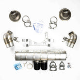
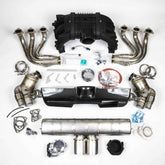
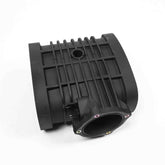
991 GT3 Center Plenum - Flap Removal and Installation
This document contains information regarding the flap removal process out of a 991 GT3.


Created by: Anthony Butay date: 05/27/2019
Edited by: Eric Rosu date: 07/22/2020
Introduction
This document contains information regarding the flap removal process out of a 991 GT3. Both the regular GT3 and the GT3RS have the same plenum variant. The difference between the plenums is when the new 991.2 came out. Therefore, there will be some instructions that are 991.1 or 991.2 specific, pay attention to this as I will specify this case in the procedure below.
Tools Required

- ¼” drive ratchet
- ¼” drive torque wrench
- 8-12” long ¼” drive extension
- ¼” drive 4mm hex bit
- ¼” drive T25 torx bit
- ¼” drive T30 torx bit
- Flathead screwdriver
- 90° pick
- Long needle nose pliers
- Pry bar
- Long 20” ½” drive extension (this is to install a bushing; a long pry bar will also work)
Flap and MAP Removal
Below are the parts shown that will be removed from the stock center plenum out of your 991 GT3. The MAP sensor is also removed from the stock center plenum, it is not shown below. The 991.1 GT3/GT3RS only has the small flap, shown in the small box below on the left side. The 991.2 GT3/GT3RS uses both the large flap and the small flap shown below. There is going to be some 991.2 specific instruction in the procedure below.


1. After the stock center plenum has been removed from the car, take the stock 991 GT3 center plenum, the ¼” drive ratchet, short extension, and T30 torx bit. Remove the screw holding the MAP sensor in the plenum and remove the MAP sensor. Set this part aside for now.


2. Using the same center plenum we used in step 1, grab the ¼” drive ratchet, short extension, and T25 torx bit. Remove the lower vacuum actuator screws from the center plenum. After this is completed, carefully pop the ball socket off of the flap. Set the vacuum actuator and screws aside for now. The center plenum should look like it does in STEP 4 below when done.


3. Now that the flap vacuum actuator has been removed we can now remove the small flap. There is a small tab that we have to get the 90° pick underneath in order to remove the flap shaft. The tab is located in the red box in the picture below. After locating the tab, slide the 90° pick underneath it, CAREFUL WITH THIS STEP AS THE TAB IS BRITTLE AND CAN BREAK. If the tab does happen to break it is okay as we have a solution for it. Now pull the flap shaft out while the pick is still underneath the tab.


4. After the flap and flap shaft have been removed, it is time to remove the bushing that the flap shaft goes through. Carefully remove the plastic bushing using the flathead screwdriver. It has to be pushed into the plenum in order for the bushing to be removed.


5. STOP IF YOU HAVE A 991.1. YOU ARE NOW COMPLETED WITH THE FLAP REMOVAL PROCESS. MOVE ONTO THE FLAP INSTALLATION PROCESS. YOU WILL HAVE THE MAP SENSOR AND THE PARTS FOR THE LOWER SMALL FLAP
991.2 Specific Flap Removal Below (steps 6-10)
6. Take the center plenum, grab the ¼” drive ratchet, short extension, and T25 torx bit. Remove the rear vacuum actuator screws from the center plenum. After this is completed, carefully pop the ball socket off of the flap. Set the Vacuum actuator and screws aside for now.

7. The rear flap needs a more forceful method for removal. Grab the center plenum and the pry bar as shown below. We are going to pop the flap out in this motion. Pry against the spot the vacuum actuator mounts to and push the flap in the upward direction. This flap is grabbing the flap shaft tightly, so a good amount of force is required to get the flap shaft to pop out of the flap.

8. Now we can grab the flap shaft and remove it from the center plenum. After the flap shaft is pulled completely out, we can remove the flap out of the side of the plenum as well.

9. After the flap and flap shaft have been removed it is time to remove the bushing that the flap shaft goes through. Carefully remove the plastic bushing using the flathead screwdriver. It must be pushed into the plenum in order for the bushing to be removed.


10. You should have all the pieces shown below now in addition to the MAP sensor and screw. The disassembly stage of factory plenum is now complete.

Flap and MAP Installation
We will now install the flaps and MAP sensor of the stock center plenum into the new Dundon Motorsports Center Plenum and larger throttle body.

1. Take the Dundon Motorsports center plenum and set the piece in front of you. The first part to install into the new center plenum is the MAP sensor. Grab the MAP sensor, ¼” drive ratchet, short extension and T30 torx. Install the MAP sensor as shown below.

2. The lower flap installation will be up next. Grab the center plenum, the small flap shaft, and small brass bushing. Place the bushing onto the small flap shaft as shown below. Feed the lower flap shaft into position while keeping the brass bushing on the flap shaft. Carefully push the brash bushing into position in the lower flap bushings hole. THIS DOES NOT NEED A LOT OF FORCE. The bushing should slide in easily. The bushing should be in the hole now part of the way, now remove the flap shaft partially and push the bushing the rest of the way in with the flap shaft. Set the flap shaft aside for now. The pictures showing this whole process are below.


3. The plastic bushing from the stock center plenum will be the next thing to install. Apply a generous amount of motor oil onto the rubber seal, we are trying to get the seal to not grab onto the plenum itself. Grab the edge of the plastic bushing as shown with the long needle nose pliers. Insert the bushing into the side opposite to the brass bushings we just inserted. Now we need to grab the long pry bar or the extension as stated in the tools used, slide the long extension or pry bar into the plenum as shown. Push the plastic bushing all the way into the plenum. Moving the pry bar or extension and wiggling the bushing in will help get it seated. If the bushings won’t stay all the way in it is okay, we will just need to push it aside when we install the flap.


4. Below is shown how the flap is aligned with the flap shaft and also the way the flap goes onto the flap shaft. The round hole side of the flap goes toward the brass bushing inside the plenum. The ball joint on the flap shaft should be aligned with the small flap. We are now ready to install the flap inside the plenum. Hold the flap with the long needle nose pliers and feed the flap into the middle of the small flap cavity. While holding the flap with the long needle nose feed the flap shaft in until the flap clicks in. If you broke the tab on the flap, just push the flap shaft all the way in. The installed position is shown at below. The flap should be open in this position and open if you look inside.


5. Now that the flap is installed completely, it is time to install the flap retainer and vacuum actuator from the stock plenum. Grab the ¼” drive ratchet, short extension and 4mm hex bit. Using two 6mm*18mm long button head screws screw in the flap retainer. Torque these bolts to 50 Deci-NM (44 in-lb) with the torque wrench.

6. Attach the vacuum actuator onto the ball joint and screw the vacuum actuator to the plenum. DO NOT OVER TIGHTEN THESE BOLTS. They will tighten down ok, just remember that you are threading into plastic.

7. STOP - STEPS 8 AND 9 WILL BE FOR 1 GT3/GT3RS ONLY. IF YOU HAVE A 991.2 MOVE ONTO STEP 10.
8. Grab the flap block off plate and 23mm O-ring. Place the O-ring into the flap block off O-ring groove. Also grab the ¼” drive ratchet, short extension, 4mm hex bit and two 6mm*18mm long button head screws. Screw the flap block off with O-ring onto the back of the plenum, Torque the two hex button head screw to 50 Deci-NM (44 in-lb).

9. The flap installation is now complete and the plenum is ready to be installed in the car. The plenum should look as it does below. At the end of the 991.2 flap installation there is a picture of how the throttle body attaches to the plenum. This is there to show you how the various gaskets and plate is installed, along with a torque spec.

991.2 Specific Flap Installation Below (Steps 10-15)
10. Repeat steps 2-4 (shown in 11-13) for the rear flap assembly. Below will be pictures showing how to do the rear flap, however it will not be described as it was before.
11. Repeat Step #2 from earlier


12. While holding the flap inside the large flap cavity, insert the flap shaft, while making sure that the ball joint is in the orientation shown below.

13. Install the vacuum actuator ball joint and screw the vacuum actuator to the plenum.

The plenum is now ready to install into your 991.2 GT3/GT3RS. It should have the vacuum actuators installed as shown in the pictures above.
Throttle Body Install
The throttle body above is installed once the center plenum is in the car. Make sure the O-ring is well seated. Using your stock throttle body off the old plenum, install new throttle onto plenum. THIS IS A 2-STEP TORQUE PROCESS. The throttle body bolts need to be torqued with an E10 socket to 70 Deci-NM. Let the plenum sit for 15 minutes with the throttle body torqued on. Loosen the bolts. Re-torque the throttle body bolts to 75 Deci-NM.


