


992 GT3/RS Street Header Install Instructions
This document contains information regarding the removal of the 992 factory muffler and installation of Dundon 992 street header and lifetime muffler.

IMPORTANT NOTE: The electronic valves NEED to be calibrated with a PIWIS 3 Tool after the new exhaust is installed and before starting the car. Failure to do so can result in damage to your exhaust and will void your Dundon Warrranty.


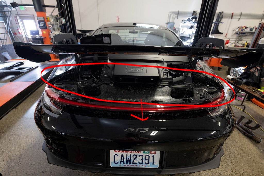


6. The lower tail light can now be removed. There are 2 T30s holding this light in, the one on the right has a metal sleeve surrounding the bolt this piece is not captured and can be lost easily. Repeat for driver side.

7. Disconnect bumper plugs behind lower tail light, there is one on the driver side and 2 on the passenger side.


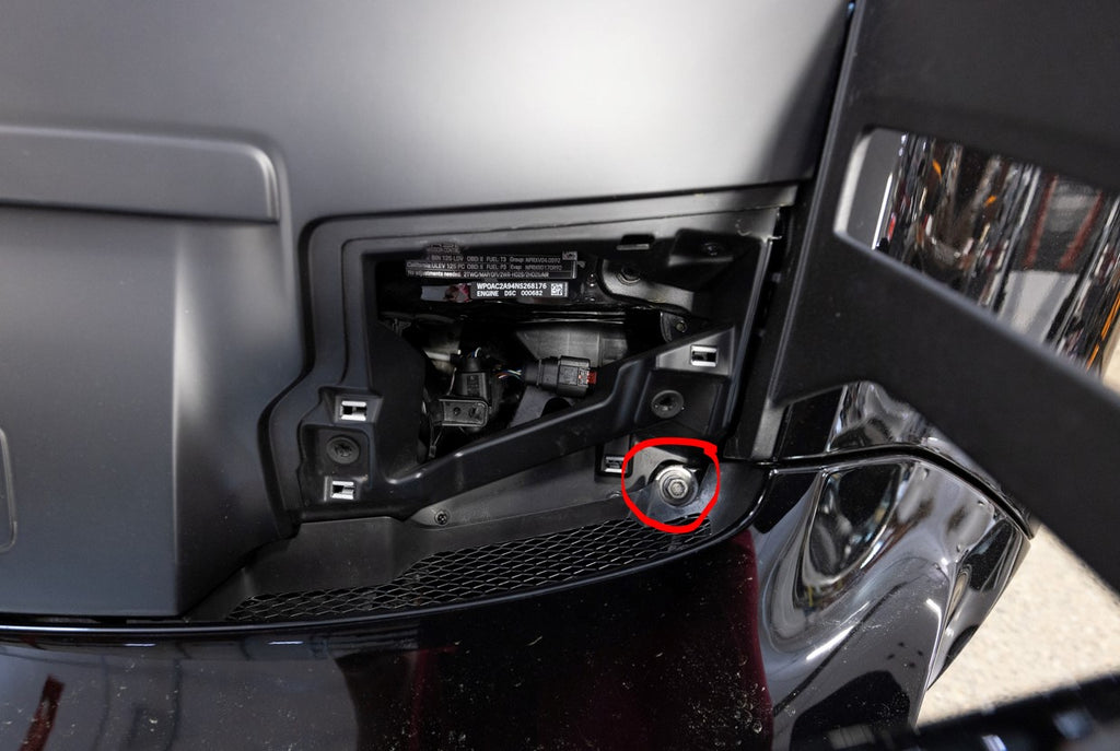
8. The rear wheels now need to be removed to help make the bumper removal easier. Once the wheels are removed, remove the rear inner fender liners (4 T25 Torx and 1 10mm plastic nut) and 1 10mm plastic nut that is holding the second fender liner onto the chassis. There is a bumper bolt (red arrow in 3rd picture) that is a lot easier to get to once removed. Repeat for other side.


9. Remove 3 T30 Torx screws that hold the bumper on behind wheel liner.


10. Remove lower diffuser (3 T30 Torx screws). Bolts 4 and 5 can be removed 50% of the way out way and the diffuser can be slid rearward to remove diffuser. Then remove all lower T30 screws for the bumper.


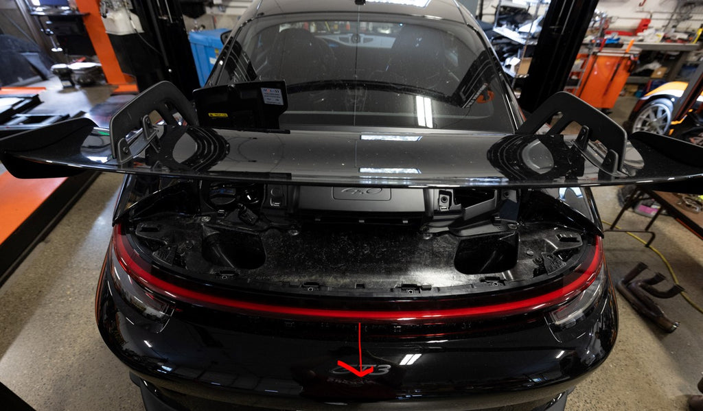
11. Remove final 2 bumper screws behind the tail lights with a helper and now the bumper can be completely removed. Pull out on the upper edge front(corner touching wheel well) of the bumper then push back toward the back of the car and the bumper will slide off the car. We recommend having two people perform this job.


13. Place a screw jack underneath the muffler to support the muffler, This is also a place where a second person is convenient for an extra hand. Unscrew the M6 bolts for the muffler straps at least have way out so you can get the bolt out of the cradle, push the straps off of the muffler bracket to allow the muffler to come off of the car. Unplug both passenger and driver E-valve connectors that are plugged into the muffler.

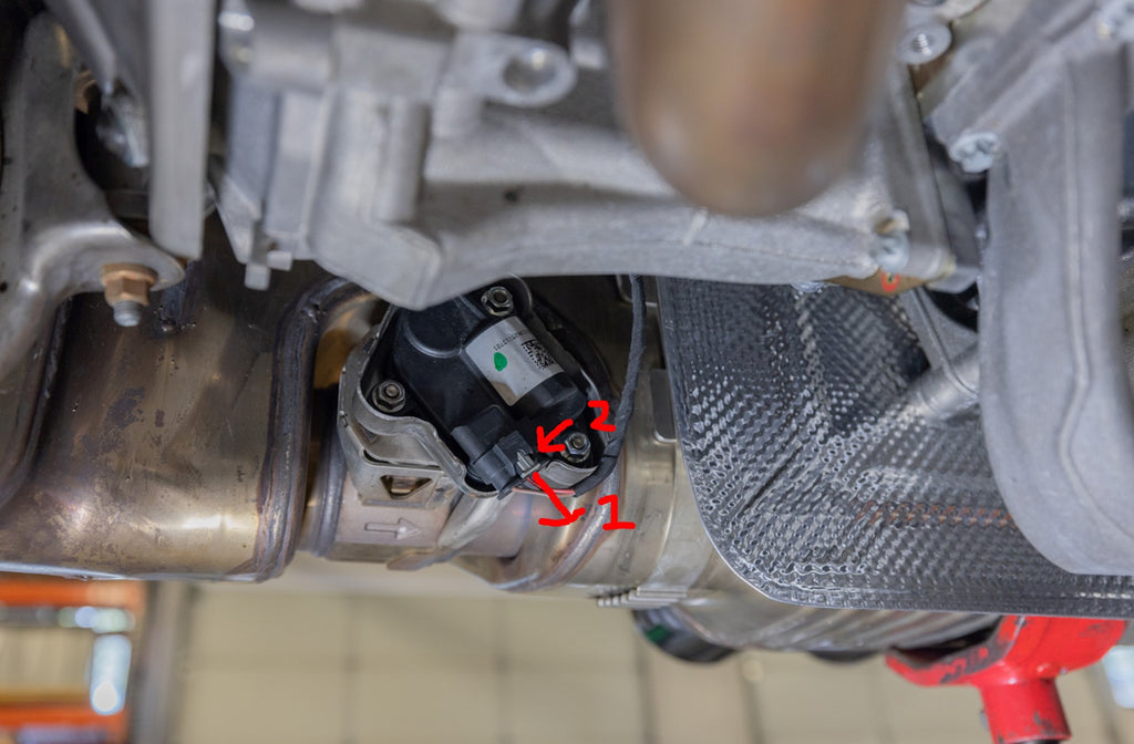
14. Remove the bolt that holds the muffler to each OPF bank 1 and 2. This is an M6 hex bolt. These is a nut on the backside that is loose so be careful not to lose this.

15. At this point the muffler is just being held by the screw jack, grab another person and remove the muffler from the car, this may take a bit of wiggling to get it loose from the OPF outlets. Careful to also get the clamps for the OPF outlets free as you are removing the muffler.

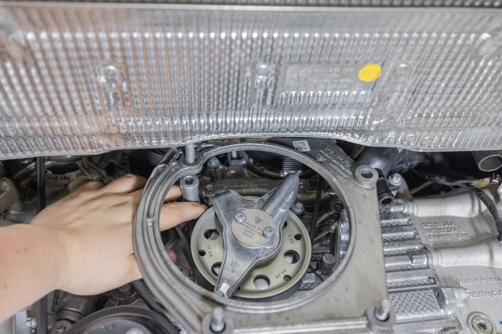
16. Remove the OEM muffler bracket. The upper bolt can be reached through the frame with a long extension and socket

17. There is a spacer for the upper bolt, when removing the muffler brackets be careful not to lose this spacer


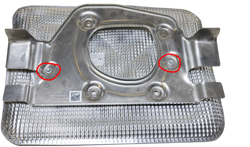
18. Remove the heatshield from the OEM muffler bracket and install on the new supplied muffler bracket. Washers for the heatshield go on the backside of the muffler bracket as shown below.


19. Install the new supplied muffler bracket with heatshield now installed onto the car. Put new supplied M10 washer on the upper left bolt when installing the bracket shown in the picture below. Remember the spacer also needs to be installed behind the engine brace. Torque to spec.

20.Disconnect 02 sensors from chassis on both sides and feed the wires down so the OPF assemblies can be removed from the car.


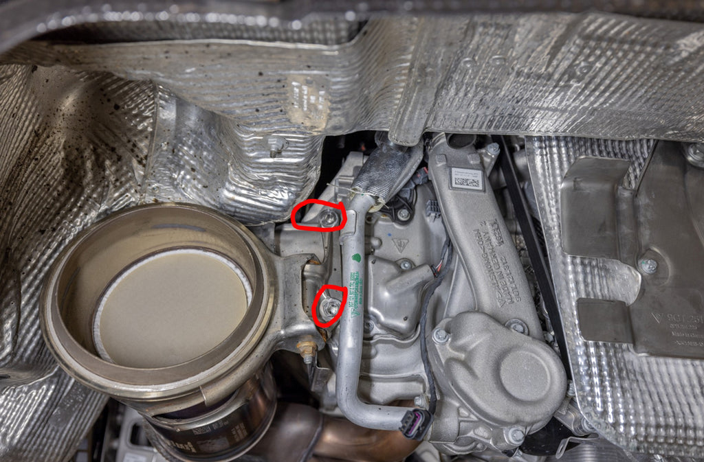
21. Remove the E12 bolts from the brackets that help support the OPF assemblies on each side of the car.

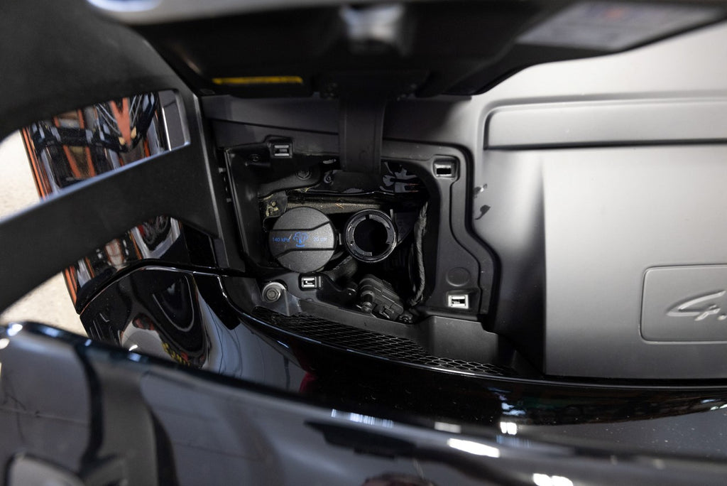
22. Remove the Oil tank heatshield on the passenger side of the car.

23. Bend the ground cable slightly to allow more space to the new headers once installed.

24. Remove each bank OPF assemblies.
25. Unthread 02 sensors from the OPF assemblies and put them into the new catalysts. The blue wire is the primary sensor and need to go on the straight cone side of the catalyst. The black 02 sensor goes on the offset cone (cast cone side). See picture below.

26. Remove electronic actuators from the OEM muffler and put onto the new valve assemblies. There is a spring that needs to be installed into the valve and then the electronic actuator can be installed. If the spring in the valve assembly does not line up with electronic actuator, a screwdriver may be needed to assist in getting the part installed. The computer will be able to adjust later, however we do not want to try and rotate the electronic part.


The actuator below is not completely aligned, here is how we deal with this.


27. Diffuser Ducts Installation instructions

WHAT IS INCLUDED?


2. Prepare Dundon 992 GT3/RS Diffuser Ducts for installation

3. Put 992 Diffuser Duct – Main Body (RIGHT) on the metal duct

4. Put 992 Diffuser Duct – Cap (RIGHT) on the metal duct
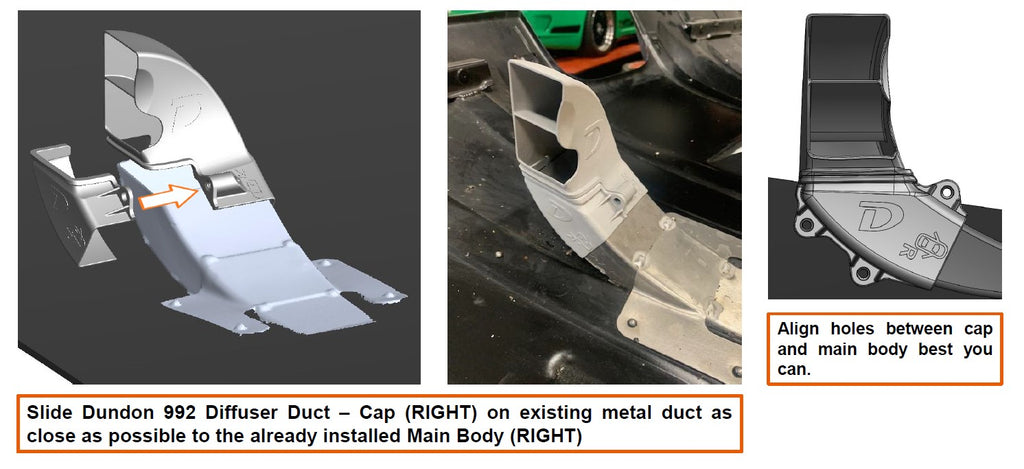
5. Put and fasten 3x M5 bolts

6. Put 992 Diffuser Duct – Main Body (LEFT) on the metal duct

7. Put 992 Diffuser Duct – Cap (LEFT) on the metal duct


Bank 1 (Driver's side on LHD cars) 02 sensor wire routing:


Bank 2 (Passenger side on LHD cars) 02 sensor wire routing:


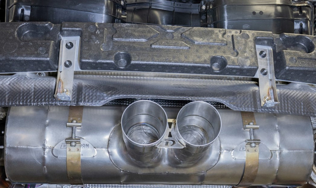
The line above is not completely straight, however the valves going into the muffler should form a straight line into the muffler and across to the other side. You can move the muffler left and right to get it centered to you liking, the height of the muffler is more dependent on the angle of the valves going into the muffler.
33. At this point every part for the headers should be installed onto the car loosely, v-band clamps should be clamped, on the parts, all bolts installed, donut gaskets for muffler etc. NO PART SHOULD BE TORQUED DOWN with the exception of the electronic actuators. Below is a picture of Bank 2, please follow the steps below in order, the picture is just an example. Tighten down the components in the following order

- Bank 2 Header flanges to cylinder head (30 Nm)
- Bank 1 Header flanges to cylinder header (30 Nm)
- Bank 2 V-band clamp from cat to header down about 50% of available threads
- Bank 1 V-band clamp from cat to header down about 50% of available threads
- Bank 2 V-band clamp from cat to valve down about 50% of available threads
- Bank 1 V-band clamp from cat to valve down about 50% of available threads
- Bank 2 muffler inlets torque donuts down all the way to 30 Nm
- Bank 1 muffler inlets torque donuts down all the way to 30 Nm
- Tighten Bank 2 muffler strap
- Tighten Bank 1 muffler strap
- Finish tightening down V-band clamps to ensure there are no air leaks getting into the system.
- Bank 2 catalyst bracket to engine bracket (30 Nm)
- Bank 1 catalyst bracket to engine bracket (30 Nm)
- Go back and tighten down the V-band clamps and make sure these are now tightened completely
Enjoy your new exhaust!!
It is normal for things to expand and contract after a few heat cycles. Ensure you check the torque of all fasteners after a spirited drive and a tank of gas has been consumed.